Chapter 1: The Basics of Networking

بسم الله الرحمن الرحيم , اللهم صلي و سلم و بارك علي سيدنا محمد صلي الله عليه وسلم
To attack network protocols, you need to understand the basics of computer networking.
This chapter is about introduction to basic network concepts that you’ll encounter every day when you’re analyzing network protocols.
Arabic Resource to Network basics from (22–29): Hassan Saad
English Content: Playlist
1.1 Network Architecture and Protocols
Let’s start by reviewing some basic networking terminology.
What is a network?
A network is a collection of interconnected devices (such as computers, smartphones, printers, etc.) that can communicate with each other, and access information. It allows devices to exchange data and communicate with one another, either through wired or wireless connections.
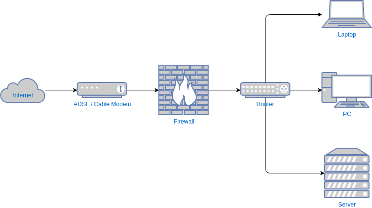
The image shows many devices that connected to same network, Each device node might have a different operating system or hardware. But to establish connection every note follows some or set of rules, or network protocol to communicate correctly via network.
A network protocol serves many functions, including one or more of the following:
Maintaining session state: Protocols help establish and terminate connections between devices on a network.
Identifying nodes through addressing: They include mechanisms to identify specific devices or groups of devices on the network.
Controlling flow: Protocols manage data flow to optimize speed and reduce delays in transmission.
Guaranteeing the order of transmitted data: They ensure that transmitted data arrives in the correct sequence.
Detecting and correcting errors: Protocols detect and ideally correct any data corruption during transmission.
Formatting and encoding data: They define how data is structured and encoded for transmission.
1.2 The Internet Protocol Suite
TCP/IP, which stands for Transmission Control Protocol/Internet Protocol, is a set of networking protocols used for communication on the internet and other interconnected networks.
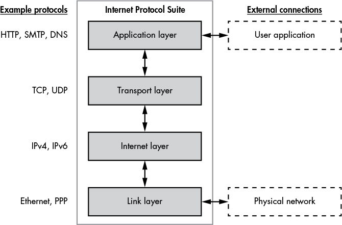
These four layers form a protocol stack. The following list explains each layer of the IPS:
Link Layer (Layer 1): Handles the physical transfer of data between devices on a local network. Examples include Ethernet and Point-to-Point Protocol (PPP).
Internet Layer (Layer 2): Provides mechanisms for addressing network nodes, even if they’re not on the local network. It includes protocols like IPv4 and IPv6.
Transport Layer (Layer 3): Manages connections between clients and servers, ensuring packet order and supporting multiple services through port numbers. TCP and UDP operate here.
Application Layer (Layer 4): Contains protocols for specific network applications like HTTP for web pages, SMTP for emails, and DNS for converting names to network nodes. This layer is the primary focus of the book.
Each layer interacts only with the layer above and below it, but there must be some external interactions with the stack.
The last figure shows that the link layer interacts with a physical network connection, transmitting data in a physical medium, such as pulses of electricity or light. The application layer interacts with the user application: an application is a collection of related functionalities that provides a service to a user.
Example: An application that processes email.
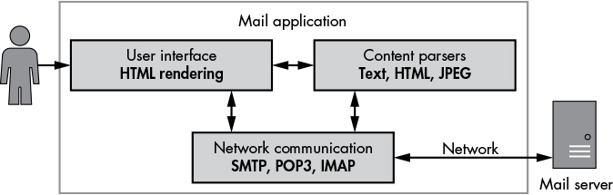
This is sample of email application that must contain the following components:
Network Communication: This part handles communication over the network using standard protocols like SMTP or POP3, typically for sending and receiving emails.
Content Parsers: Responsible for extracting and processing data from network transmissions. This can include text, images, or videos.
User Interface (UI): Allows users to view received emails and compose new ones. For example, it might display emails using HTML in a web browser. The user interacting with the UI could be a human or another application.
1.3 Data Encapsulation
Before dive in this section, we should know what is encapsulation?
Encapsulation is like putting something in a box. In programming, it’s about wrapping data and the actions that work on that data together. In networking, it’s like adding layers of packaging around data as it travels through the internet. It keeps things organized and protected.
Each layer in the IPS is built on the one below, and each layer is able to encapsulate the data from the layer above so it can move between the layers. Data transmitted by each layer is called a protocol data unit (PDU).
Imagine you’re sending a letter to a friend. In the letter, you have the actual message you want to send. Now, to make sure the letter reaches your friend correctly, you need to write down both your address and your friend’s address on the envelope. This is like adding headers to your message in networking.
Now, sometimes, to make sure nothing goes wrong during the journey, you might want to add some extra information at the end of your letter, like a seal. This is similar to adding a footer in networking, which contains error-checking information.
In computer networks, when we talk about sending data, we use terms like PDUs (Protocol Data Units) to describe these packets of information. Each layer of the network adds its own header and sometimes a footer to the data being transmitted.
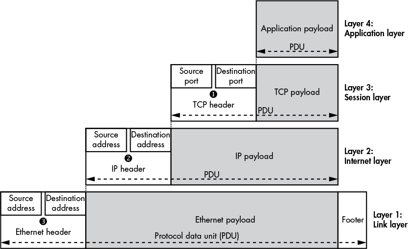
Some Notes Describe this image:
The TCP header contains a source and destination port number ➊. These port numbers allow a single node to have multiple unique network connections.
Port numbers for TCP (and UDP) range from 0 to 65535. Most port numbers are assigned as needed to new connections, but some numbers have been given special assignments, such as port 80 for HTTP.
To find assigned port number list you can find it at
/etc/servicesfile on most Unix-like operating systems.A TCP payload and header are commonly called a
segment, whereas a UDP payload and header are commonly called adatagram.The IP protocol uses a source and a destination address ➋. The destination address allows the data to be sent to a specific node on the network. The source address allows the receiver of the data to know which node sent the data and allows the receiver to reply to the sender.
IPv4 uses 32-bit addresses, which you’ll typically see written as four numbers separated by dots, such as 192.168.8.1
IPv6 uses 128-bit addresses, because 32-bit addresses aren’t sufficient for the number of nodes on modern networks. such as fe80:0000:0000:0000:897b:581e:44b0:2057
Ethernet also contains source and destination addresses ➌. Ethernet uses a 64-bit value called a Media Access Control (MAC) address such as 0A-00–27–00–00–0E
Data Transmission
This section take about how data transferred from one node to another using the IPS data encapsulation model.
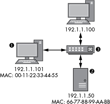
In this example, the node at ➊ with the IP address 192.1.1.101 wants to send data using the IP protocol to the node at ➋ with the IP address 192.1.1.50. (The switch device ➌ forwards Ethernet frames between all nodes on the network. The switch doesn’t need an IP address because it operates only at the link layer.)
There’re steps of how data moves under this network:
The operating system network stack node ➊ encapsulates the application and transport layer data and builds an IP packet with a source address of 192.1.1.101 and a destination address of 192.1.1.50.
Now the operating system doesn’t know the MAC address of the destination node, it sends an ARP request to find it. This request is broadcast to all nodes on the network, since receiving the ARP request, the destination node replies with its MAC address.
Once the node at ➊ receives an ARP response, it can build the frame, setting the source address to the local MAC address of 00–11–22–33–44–55 and the destination address to 66–77–88–99-AA-BB. The new frame is transmitted on the network and is received by the switch ➌.
The switch forwards the frame to the destination node, which unpacks the IP packet and verifies that the destination IP address matches. Then the IP payload data is extracted and passes up the stack to be received by the waiting application.
1.4 Network Routing
- Is like finding the best way for a message to travel from one place to another on the internet. Just like you might use GPS to find the quickest route to a friend’s house, routers on the internet decide the best path for data packets to reach their destination. They look at things like traffic, road conditions, and the distance to pick the fastest or most reliable path. Routing helps ensure that your emails, videos, and web pages reach their destination quickly and safely.
This may help : https://youtu.be/gQtgtKtvRdo?si=u4UIjIE_898z9pmD
1.5 My Model for Network Protocol Analysis
We know that IPS describe how network communicate with each other.
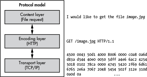
Here are the three layers of my model:
Content layer Provides the meaning of what is being communicated. In image the meaning is making an HTTP request for the file image.jpg.
Encoding layer Provides rules to govern how you represent your content. In this example, the HTTP request is encoded as an HTTP GET request, which specifies the file to retrieve.
Transport layer Provides rules to govern how data is transferred between the nodes. In the example, the HTTP GET request is sent over a TCP/IP connection to port 80 on the remote node.
🚀 That’s all points that can help you in this chapter to understand more Network fundamentals see the mentioned YouTube playlist at the top of article.
❤️ Thanks to complete bro, follow me here : Twitter


